
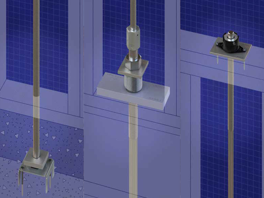
Strong-Rod® Anchor Tiedown System Canada
Simpson Strong-Tie Strong-Rod Systems have become a popular continuous rod tiedown solution for light-frame, multi-storey wood construction. Our Anchor Tiedown System for Shearwall Overturning Restraint and our Uplift Restraint System for Roofs address many of the design challenges specifically associated with multi-storey buildings that must withstand seismic activity or wind events.
Contact Simpson Strong-Tie for more information or to request Design Services.
Your Full-Solution Partner for Anchor Tiedown Systems in Canada
Multi-storey structures require a variety of special design considerations, and having a reliable, highly knowledgable design partner is critical to keeping projects on time and within budget. No company knows lightframe wood construction better than Simpson Strong-Tie, and we have everything you need to design your building. ATS components and systems that come with unmatched testing and design expertise are your formula for success.
Let Simpson Strong-Tie be your partner in designing the safest building possible with materials suited specifically for the application, making installation easier and costs lower. To find out how we can help you, fill out a Request for Information or call (800) 999-5099.
Learn About our U.S. Strong-Rod Systems
Simpson Strong-Tie Strong-Rod Systems have become a popular continuous rod tiedown solution for light-frame, multi-storey wood construction. Our Anchor Tiedown System for Shearwall Overturning Restraint and our Uplift Restraint System for Roofs address many of the design challenges specifically associated with multi-storey buildings that must withstand seismic activity or wind events.
Strong-Rod Systems Seismic and Wind Anchor Tiedown System Guide
A Canadian limit states design catalogue for Strong-Rod Anchor Tiedown Systems. Includes product information, design methods, and pre-engineered runs using shrinkage compensation and other components.