SSC Steel-Stud Connector
Bridging and Bracing Connectors
This product's information may differ depending on the category of use. You are currently viewing details related to Bridging and Bracing Connectors. You can also view product information related to the categories of: Rigid Connectors for Cold-Formed Steel Construction, Roof Truss and Rafter Connectors, Ties, and Straps for Cold-Formed Steel Construction
Product Details
SSC connectors are versatile utility clips ideal for a variety of stud-to-stud and stud-to-structure applications in cold-formed steel construction. The clips have been designed to enable easy installation on the open side of studs or joists with flanges up to 3" long and return lips up to 3/4". A wide pattern of strategic fastener locations allows the SSC to accommodate a variety of traditional and custom designs.
Key Features
- Prepunched holes reduce installation cost by eliminating predrilling
- Intuitive fastener hole positions ensure accurate clip installation in accordance with design, support a wide range of design and application requirements and provide installation flexibility
- Angle lengths accommodate either hard-side or soft-side attachment for studs and joists with return lips up to 3/4"*
- 4" leg length enables soft-side connections for studs and joists with flanges up to 3"*
- Also suitable for u-channel bridging
* SSC2.25 clips will accommodate 2"-wide flange and 5/8" stiffener lip
Material
- LSSC — 54 mil (50 ksi); SSC — 68 mil (50 ksi); MSSC — 97 mil (50 ksi)
Finish
- Galvanized (G90)
Installation
- Use all specified fasteners/anchors
Patent Information
- US Patent 9,091,056
Related Literature
Product Information Table
| Model No. | Thickness (mil) | Ga. | Dimensions (in.) | L (in.) | Coating/Material | Packaging Qty. |
|---|---|---|---|---|---|---|
| LSSC4.25-R50 | 54 | 16 | 2 1/4 x 4 | 4 1/4 | Zinc Galvanized, G90 | 50 |
| LSSC6.25-R30 | 54 | 16 | 2 1/4 x 4 | 6 1/4 | Zinc Galvanized, G90 | 30 |
| MSSC2.25-R90 | 97 | 12 | 2 1/4 x 3 | 2 1/4 | Zinc Galvanized, G90 | 90 |
| MSSC4.25-R50 | 97 | 12 | 2 1/4 x 4 | 4 1/4 | Zinc Galvanized, G90 | 50 |
| MSSC6.25-R30 | 97 | 12 | 2 1/4 x 4 | 6 1/4 | Zinc Galvanized, G90 | 30 |
| SSC2.25-R125 | 68 | 14 | 2 1/4 x 3 | 2 1/4 | Zinc Galvanized, G90 | 125 |
| SSC4.25-R50 | 68 | 14 | 2 1/4 x 4 | 4 1/4 | Zinc Galvanized, G90 | 50 |
| SSC6.25-R30 | 68 | 14 | 2 1/4 x 4 | 6 1/4 | Zinc Galvanized, G90 | 30 |
Load Tables
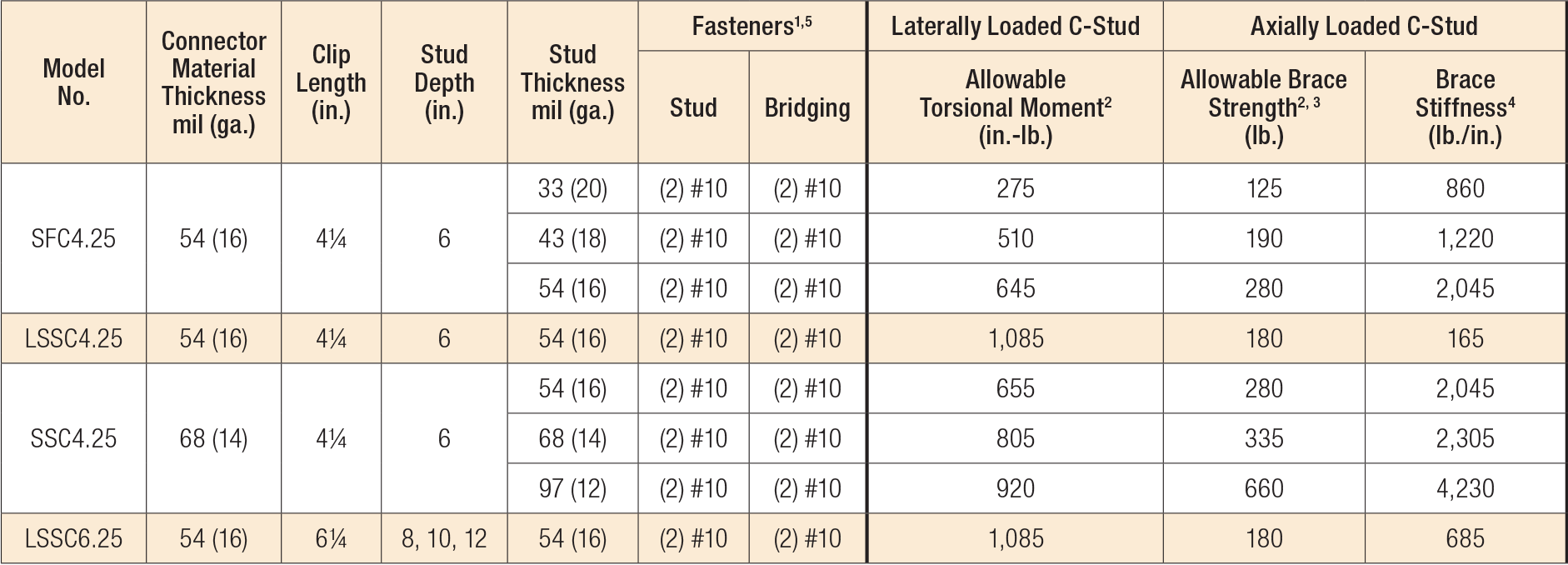
SFC/SSC Connectors – U-Channel Bridging Allowable Loads

- See illustration for fastener placement.
- Allowable loads are for use when utilizing Allowable Stress Design methodology. For LRFD loads, multiply the tabulated ASD values by 1.6.
- Allowable brace strengths are based on ultimate test load divided by a safety factor. Serviceability limit is not considered, as brace stiffness requirements are given in Section C2.3 of AISI S100. Contact Simpson Strong-Tie if nominal brace strength is required.
- Tabulated stiffness values apply to both ASD and LRFD designs.
- See Fastening Systems for more information on Simpson Strong-Tie fasteners.

Typical SSC4.25 Installation
Code Reports & Compliance
Drawings
| DWG | DXF | RFA | IFC | SAT | |||
|---|---|---|---|---|---|---|---|


