DSSCB Bypass Framing Drift Strut Connector
Deflection Connectors
This product's information may differ depending on the category of use. You are currently viewing details related to Deflection Connectors. You can also view product information related to the category: Drift Connectors for Cold-Formed Steel Construction
Product Details
The solution to accommodate building drift, the DSSCB, is used to support cold-formed steel bypass framing to the edge of a floor slab. The DSSCB also simplifies installation by allowing installers for panelized construction to install finished panels while working off the top of the slab without the need to predrill or preinstall anchors for each clip. It also eliminates the coordination difficulties associated with pre-anchorage of standard bypass clips. With prepunched slots and round holes, the DSSCB is a dual-function connector that can be used for slide-clip and fixed-clip applications.
Key Features
- The clips come in lengths of 3 1/2", 6" and 8".
- Prepunched slots provide a full 1" of both upward and downward deflection.
- Precision-manufactured shouldered screws, provided with DSSCB connectors, are designed to prevent overdriving and to ensure the clip functions properly.
- Works with 7/8" and 1 5/8" strut channels as given in the accompanying figures. Common manufactured brands are Unistrut®, PHD and B-Line. Struts are not supplied by Simpson Strong-Tie.
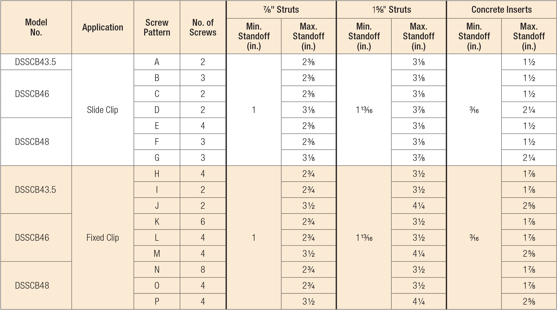
- The maximum slide-clip standoff distance is 3 1/8" for 7/8" struts, 3 7/8" for 1 5/8" struts and 2 1/4" for concrete inserts.
- Depending on the application and the designer’s specifications, struts can be either mechanically anchored, welded or cast in place.
- Pre-engineered design solutions are provided for channel strut anchorage.
- Tabulated design values are based on assembly testing to mitigate risk for designers, engineers and architects.
- Optional pre-cast concrete inserts for flush mounting.
- Optional drift stopper, DSHS, for clip alignment flexibility (where drift not required).
Material
- DSSCB — 97 mil (12 ga.), 50 ksi
Finish
- Galvanized (G90)
Installation
- Use the specified type and number of fasteners
Ordering Information
- DSHS drift stopper (DSHS-R100) sold separately
- Replacement #14 shouldered screws for DSSCB connectors are the XLSH78B1414-RP83
Patent Information
- US Patent 10,961,704
Related Literature
Product Information Table
| Model No. | Thickness (mil) | Ga. | W (in.) | Product Includes | Coating/Material | Packaging Qty. |
|---|---|---|---|---|---|---|
| DSSCB43.5-KT25 | 97 | 12 | 3 1/2 | (25) connectors; (55) XLSH78B1414 #14 shouldered screws | Zinc Galvanized, G90 | 25 |
| DSSCB46-KT25 | 97 | 12 | 6 | (25) connectors; (83) XLSH78B1414 #14 shouldered screws | Zinc Galvanized, G90 | 25 |
| DSSCB48-KT25 | 97 | 12 | 8 | (25) connectors; (110) XLSH78B1414 #14 shouldered screws | Zinc Galvanized, G90 | 25 |
Load Tables
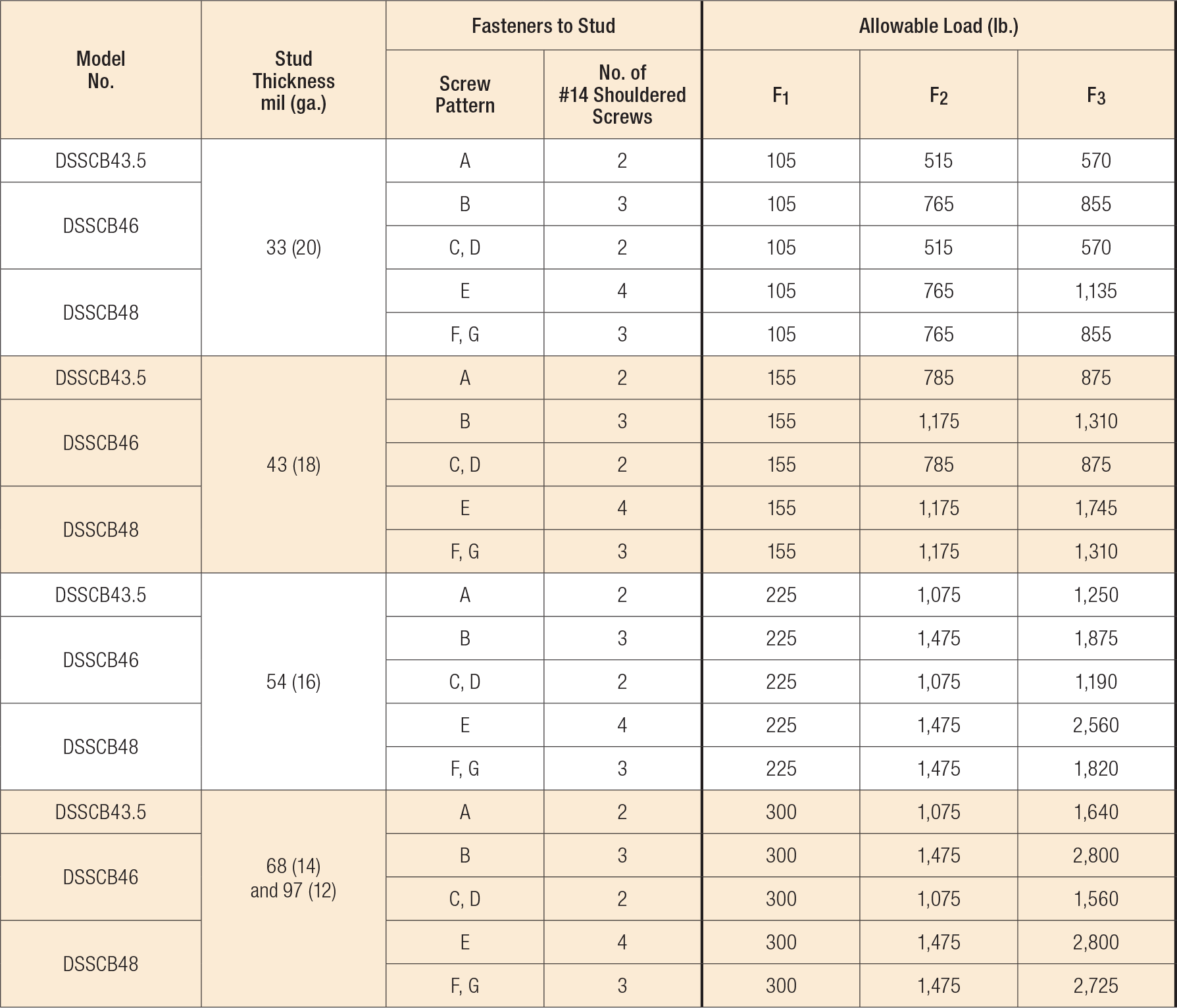
DSSCB Allowable Slide-Clip Connector Loads (lb.)

- For additional information, see Innovative Solutions for Curtain-Wall Framing.
- DSSCB Allowable Slide-Clip Connector Loads are also limited by the Strut Channel Allowable Anchorage Loads to Steel table below or Concrete Insert Allowable Anchorage Loads table below, or Strut Channel Allowable Anchorage Loads to CLT table below. Use the minimum tabulated values from the connector and anchorage load tables as applicable.
- See illustrations in the image gallery for shouldered screw fastener pattern placement to stud framing.
- Tabulated F1 loads are based on assembly tests with the load through the centerline of the stud. F1 loads require DSHS connector with (1) #10 screw to strut.
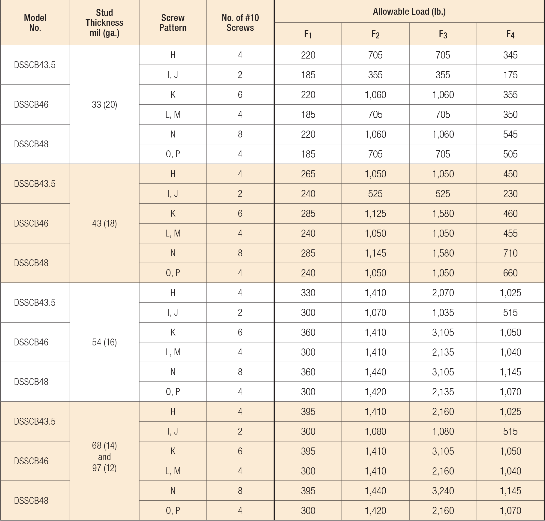
DSSCB Allowable Fixed-Clip Connector Loads (lb.)

- For additional information, see Innovative Solutions for Curtain-Wall Framing.
- DSSCB Allowable Fixed-Clip Connector Loads are also limited by the Strut Channel Allowable Anchorage Loads to Steel table below or Concrete Insert Allowable Anchorage Loads table below, or Strut Channel Allowable Anchorage Loads to CLT table below. Use the minimum tabulated values from the connector and anchorage load tables as applicable.
- See illustrations in the image gallery for screw fastener pattern placement to stud framing.
- Tabulated F1 loads are based on assembly tests with the load through the centerline of the stud. F1 loads require DSHS connector with (1) #10 screw to strut.
- In-plane capacities (F1) for DSSCB attached to 54 mil (16 ga.) stud can be increased to 455 lb. with the addition of a shoulder screw at first slot from bend line for screw pattern K and L and at middle slot for pattern M. Failure mode for this condition is member, not fastener.
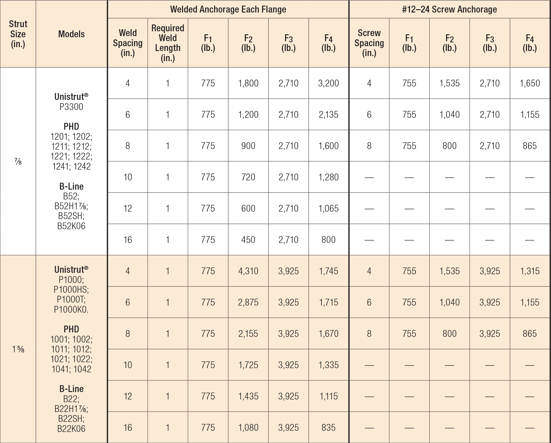
Strut Channel Allowable Anchorage Loads to Steel (lb.)

- For additional information, see Innovative Solutions for Curtain-Wall Framing.
- Allowable anchorage loads are also limited by the DSSCB Connector Load tables above. Use the minimum tabulated values from the connector and anchorage load tables as applicable.
- Allowable loads are based on 97 mil (12 ga.) thickness strut channel members with a minimum yield strength, Fy, of 33 ksi, tensile strength, Fu, of 45 ksi. Tabulated values for Unistrut P4520, 1 5/8" x 13/16" channel may be used for Unistrut channel 1 5/8" x 7/8" models P3300, P33HS and P3300T.
- Allowable loads for self-drilling screws are based on installation in minimum 3/16"–thick structural steel with Fy = 36 ksi. Values listed above may be used where other thicknesses of steel are encountered provided that the fastener has equal or better tested values into thicker steel. It is the responsibility of the designer to select the proper length fasteners based on the steel thickness installation.
- For screw fastener installation into steel backed by concrete, predrilling of both the steel and the concrete is suggested. For predrilling, use a maximum 3/16"–diameter drill bit. Screw to be installed through steel portion of channel strut (1.5 x screw diameter from punch-out) and centered vertically in web.
- For any connector occuring within 2" of channel strut splice, load not to exceed — F2 = 865 lb. and F4 = 785 lb.
- Maximum allowable load of strut can be increased at high concentrated loads by welding each flange 1" from the strut channel to support directly at clip location:
• For 7/8" strut size — F1 = 775 lb., F2 = 1,800 lb., F3 = 2,710 lb., F4 = 3,200 lb.
• For 1 5/8" strut size — F1 = 775 lb., F2 = 4,310 lb., F3 = 3,925 lb., F4= 1,745 lb. - Required weld length is on each flange at spacing indicated.
- Anchorage spacing cannot be greater than framing spacing.
- Connector load to be located a minimum of 2" from end of strut channel.
- Tabulated values for 1 5/8" x 7/8" strut may be used for 1 5/8" x 13/16" strut except F2 welded anchorage values are limited to a maximum load of 1,615 lb. If 13/16" struts are pierced, a load modifier per note 12 is required. See image gallery for all channel dimension requirements.
- F1, F3 and F4 have no load reductions for allowed piercings. F2 has no load reductions for piercings, except for welded conditions as follows:
• For 9/16" hole at 1 7/8" o.c., multiply by 0.9;
• For 7/8" hole at 6" o.c., multiply by 0.9;
• For slotted hole (1 1/8" x 9/16") at 2" o.c, multiply by 0.85.
No load reductions are required for F1, F2 or F3 load directions for allowed piercing. For images of allowed piercings reference the image gallery.
Concrete Insert Allowable Anchorage Loads (lb.)

- For additional important information, see General Notes.
- The designer is responsible for concrete slab design. The minimum tested concrete slab thickness is 8". Minimum end distance, and edge distances for concrete insert struts are shown in the image gallery above.
- Tabulated values are for concrete compressive strength f'c=4,000 psi minimum. For 3,000 psi or 3,500 psi, apply a load adjustment factor of 0.87 or 0.94, respectively.
- Allowable anchorage loads with concrete insert are also limited by the DSSCB Connector Load tables shown above. Use the minimum tabulated values from the connector and strut anchorage load table above as applicable.
- Allowable loads are based on 97 mil (12 ga.) thickness strut channel members with a minimum yield strength, Fy, of 33 ksi, tensile strength, Fu, of 45 ksi. Strut size and dimensions are illustrated in the image gallery above. Other strut manufacturer with equivalent performance and dimensions may be used as approved by the designer.
- Tabulated values are for connector load spacing at 16" minimum. Reduce load linearly for connector spacing less than 16". For example, shear connector load (F4), with 2" edge distance from the top of slab at 12" spacing is 1440 lb. * (12"/16") = 1,080 lb.
- Tabulated values are for clips installed 6" minimum from the end of strut. See minimum end distances from strut to concrete illustrated in the image gallery above.
- The load direction of shear (F4) is toward the bottom of the slab for the tabulated capacities.
- Shear load (F4) may be linearly interpolated for strut embedded between 2" from the top to 3" from the bottom of the concrete slab as follows:
• For an 8" concrete slab, shear load (F4) may be linear interpolated for strut embedded between 2" from the top and 3" from the bottom of the slab.
• For slabs thicker than 8", linear interpolate based on bottom concrete edge distance. - Allowable loads are based on testing in accordance with AC398 in Simpson Strong-Tie's IAS accredited test lab.
DSSCB Standoff Distances

Code Reports & Compliance
Drawings
| DWG | DXF | RFA | IFC | SAT | |||
|---|---|---|---|---|---|---|---|


